3D Printed
2020/07/04 categories:3D Printer| tags:3D Printer| robot_joint|
I wanted to make a 6-axis robot with a 3D printer, so I modeled an actuator for joints. However, it will be uploaded as a dead work.
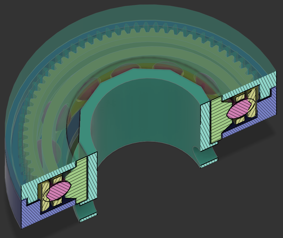
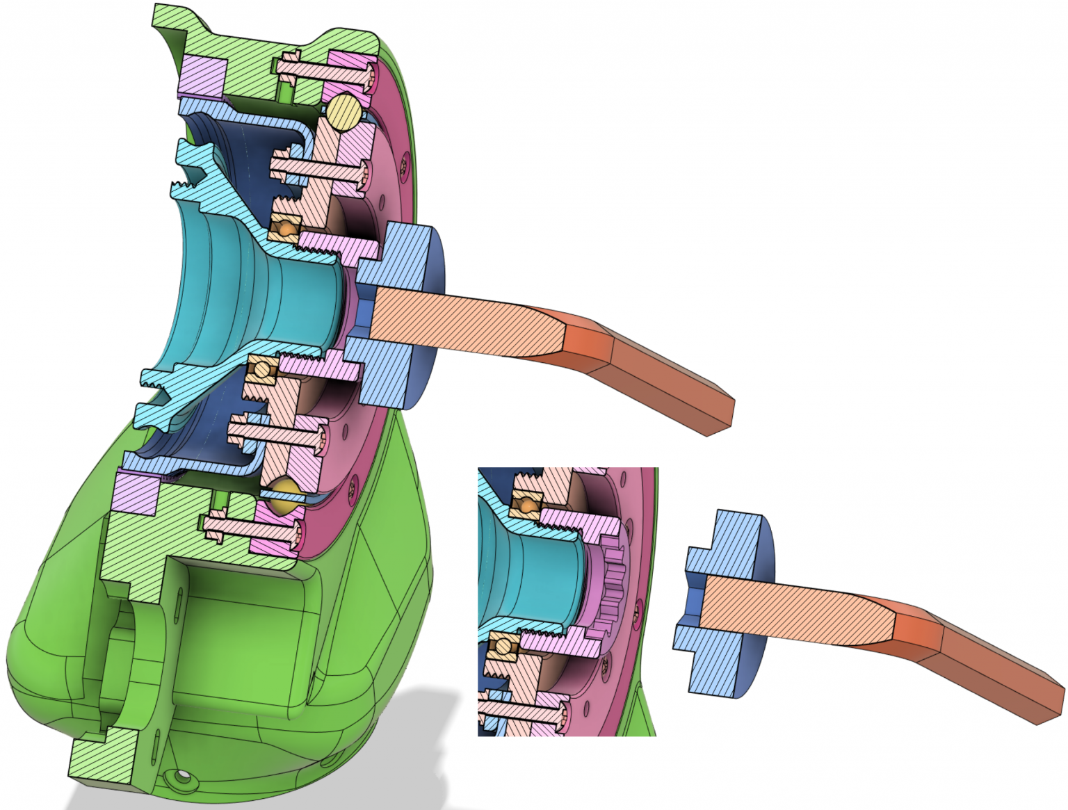
Sectional view
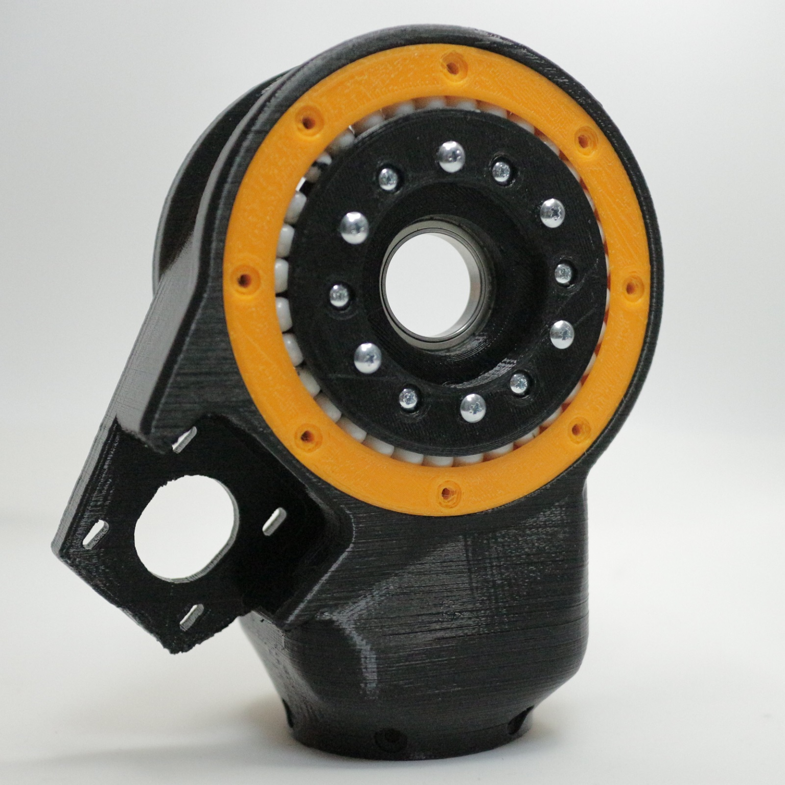
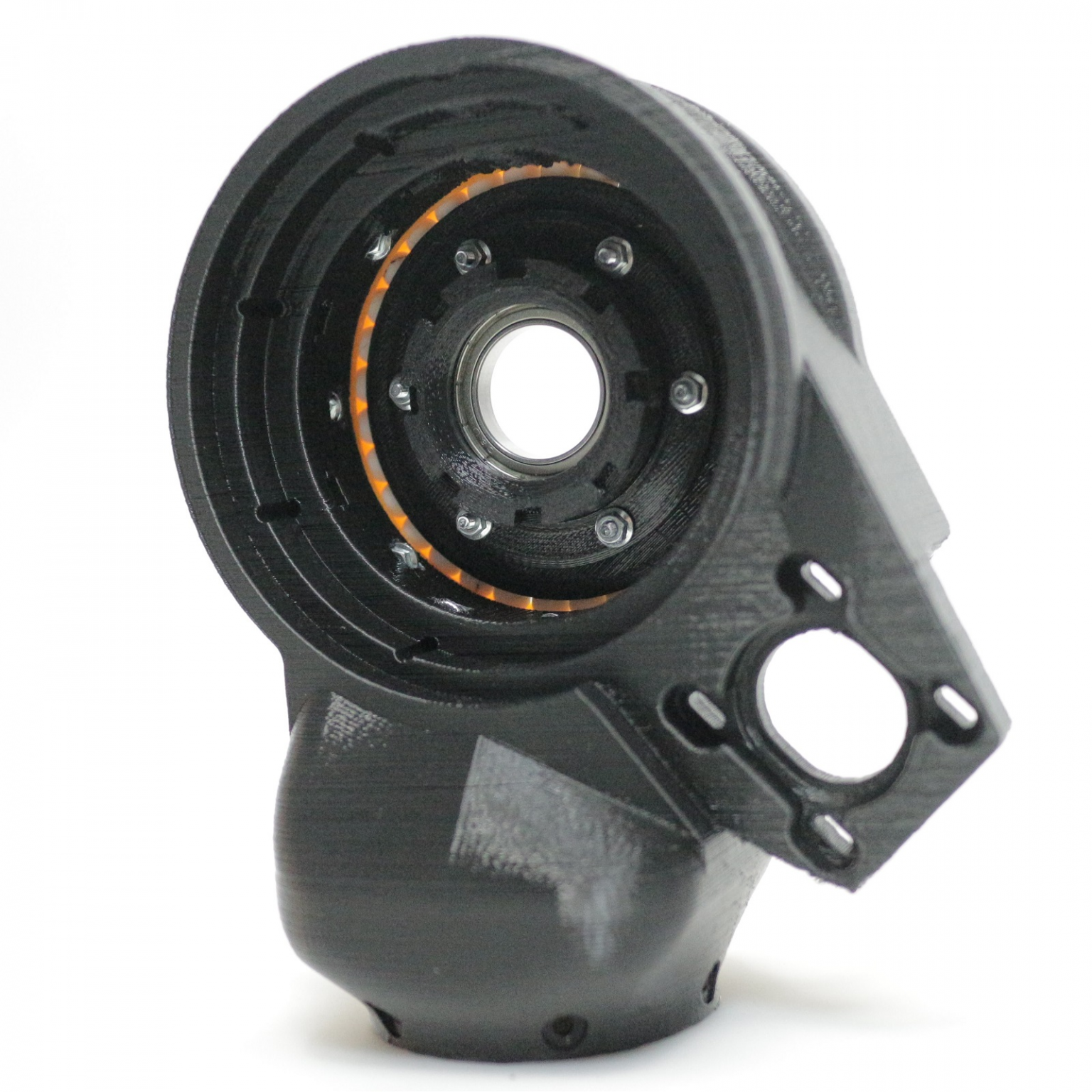
The cross section is as follows. The load applied to the joint is received by the two 3D-printed 4-point contact bearings mounted on the outermost side. One of these is a wave gear flex spline attached to the inner ring to drive the shaft. The other is used to support the wave generator and the output shaft.
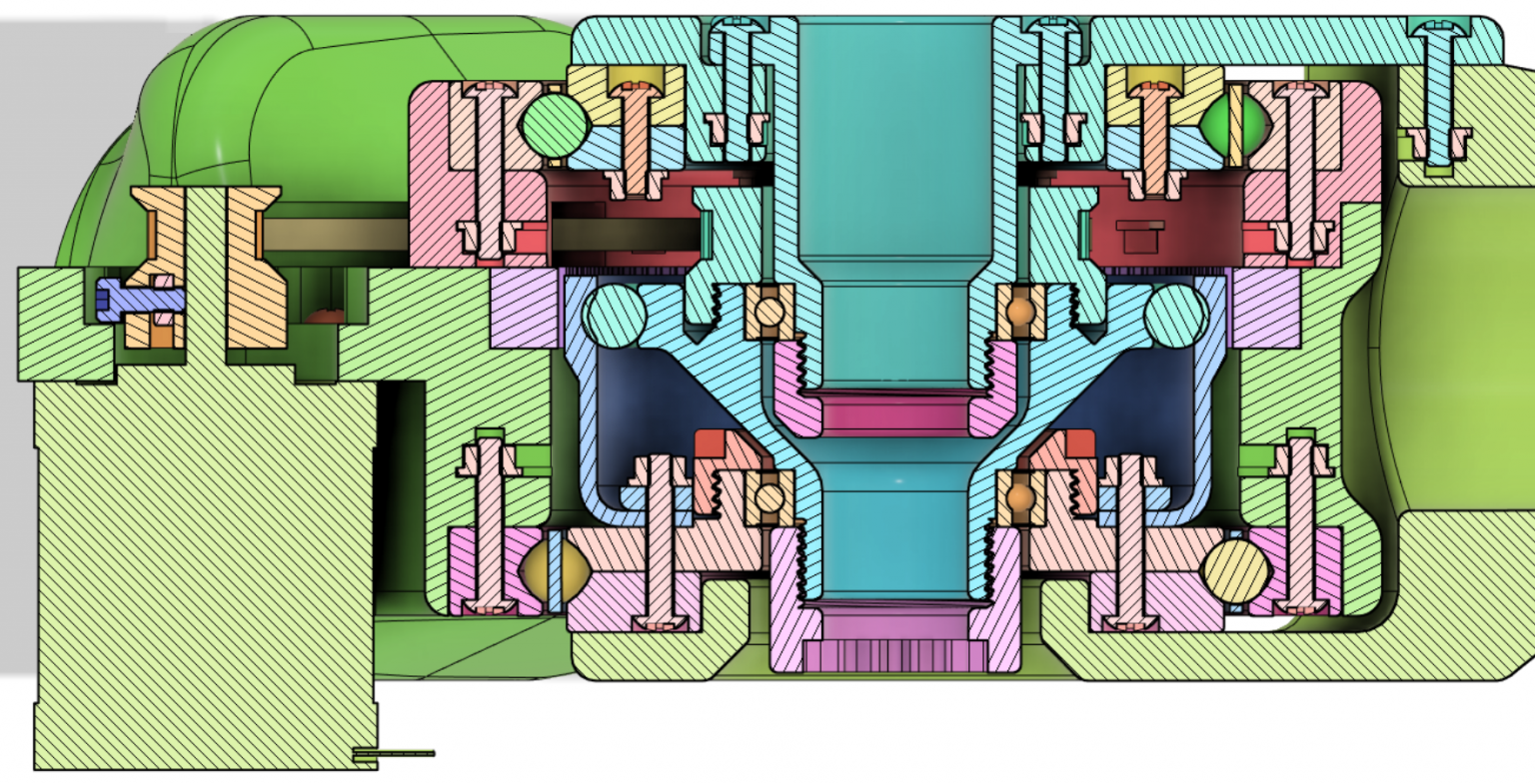
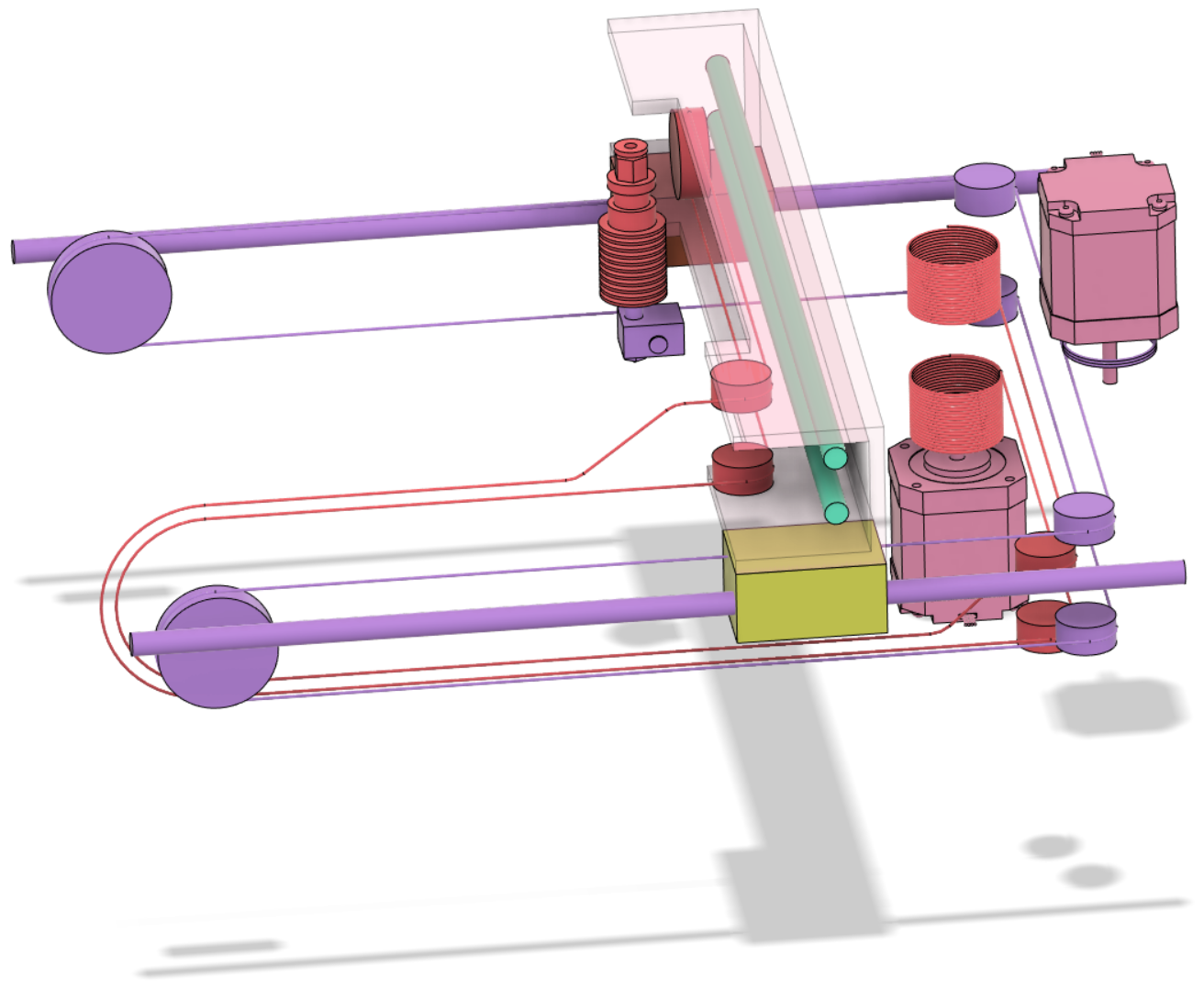
The wave generator of the wave gear is supported by 6805ZZ bearings. Furthermore, the wave generator is equipped with a timing pulley for drive transmission, and the structure is such that the drive of the motor is transmitted via a timing belt. The motor used is assumed to be NEMA17.

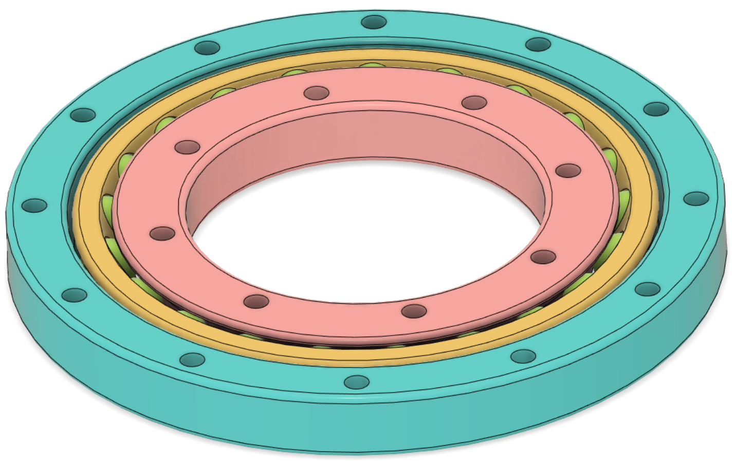
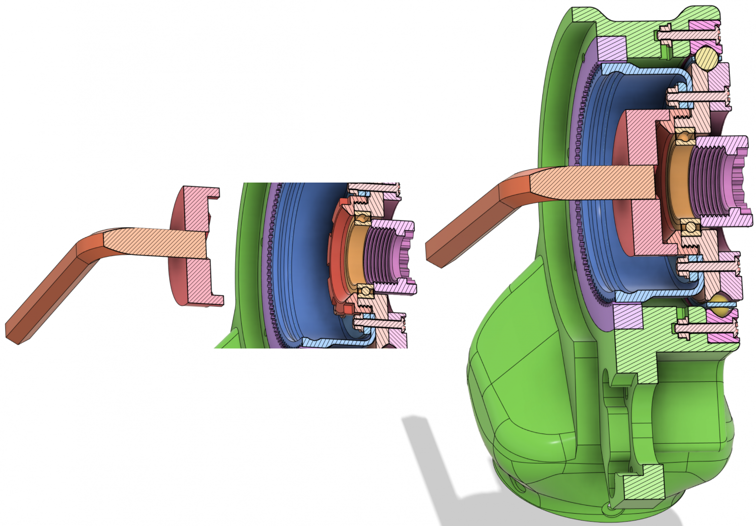
Bearing fixing
The inner and outer rings of the bearing are fixed using a locknut made with a 3D printer. Tighten the locknut using a 3D printed locknut tightening jig and a hex wrench.
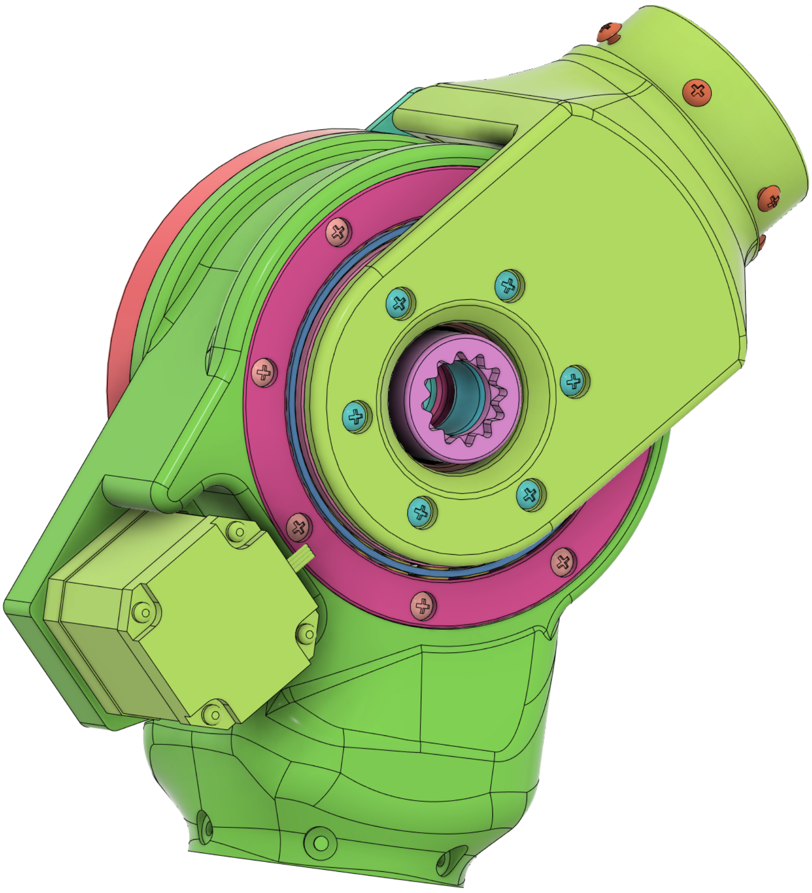
Multi-axis
Since the connection inner diameter of the joint body and the connection inner diameter of the output shaft are the same, multi-axis is possible.
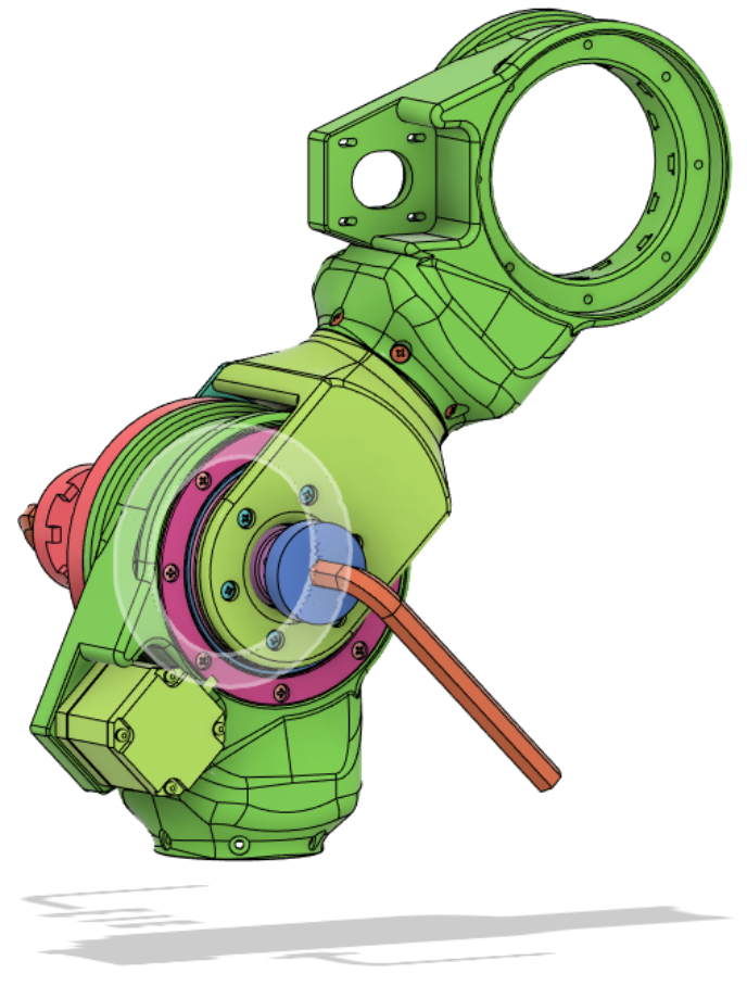
By connecting these robot joints, it is possible to configure a vertical articulated robot.

The wreckage I tried to make
3D Model
STEP file of assembly
STL Files
CIRCULAR_SPLINE_T102.stl
DownloadFLEX_SPLINE_T100.stl
DownloadJOINT_BODY.stl
DownloadJOINT_STAY.stl
DownloadWAVE_GENERATOR.stl
Download